Snappy Hex Mesh Basics #
This is a summary of meshing in OpenFOAM using the snappyHexMesh tool. I’m writing this in detail because I couldn’t find any comprehensive tutorial that is beginner friendly. The ones I could find were like as if they were picking up from where someone else left off. Consequently, this tool is a beginner guide and aims only to recommend easy-to-pickup tools, rather than the most fully featured tools. This only covers absolute basics and creating simple geometries. It only covers snappyhexMesh tool as
the user guide for the basic tool blockMesh is pretty ok.
Background #
The high-level of how snappyHexMesh works can be found here.
The basic steps are to:
- define the background mesh The background mesh is where the fluid flow will be simulated.
- create the stl file This step is to create the object you wish to insert onto the background mesh.
- run surfaceFeatureExtract This requires the system/surfaceFeatureExtractDict to be created, which defines how edges and surfaces of the stl mesh are translated into a mesh.
- run snappyHexMesh This will use the inputs created in steps 1-3. Note that setting up for running snappyHexMesh in parallel is different from running in serial (i.e., one CPU core). Both setups will be described here.
Step 1: Defining the Background Mesh #
This steps assumes that you know how to generate a simple mesh using the blockMesh utility. If you don’t follow that guide first, and work through the excercises.
The background mesh has to satisfy a few requirements:
- cells ought to be approximately cubic within the vicinity of the
stlmesh, otherwisesnappyHexMeshwill fail - the background mesh must be positioned and sized such that the
stlmesh is within it or located on the boundary
Otherwise defining a mesh in a manner described on the BlockMesh
guide is sufficient.
Step 2: Creating an stl file
#
As noted above, the stl mesh must be created in a way such that it is located inside or on the boundary of the background mesh. In addition to that, the mesh must be structured nicely (the exact requirements I’m not sure of). When I first started out, I couldn’t find a tool that created nice meshes and was also easy to use. But, instead I found tools that can create crappy meshes, and another tool that can turn these meshes into nice meshes.
Step 2a: Creating the basic shape #
This step requires a Computer Aided Design (CAD) program. I found the following CAD programs to be basic, but free and perfectly fine for basic geometries:
-
SketchUp free (
tutorial).
stlfiles can be exported using the “download” utility. -
FreeCad (
tutorial series).
stlfiles can be exported using the “export” utility.
Step 2b: Converting the mesh into something nice #
The meshes the above tools create are not guaranteed to be nice e.g., meshes produced by the above utilities will have cells that are far from being equilateral.
The tool that I found pretty easy to use and pickup is
MeshLab, but I found it to be pretty capable. To make a mesh nicer for use with snappyHexMesh, the “filters” dropdown list has a few tools that are pretty handy.

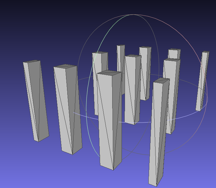
Original mesh produced by SketchUp of a baffle array (square columns). snappyHexMesh doesn’t like the small angles between lines at the corners

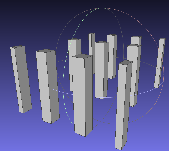
Remeshing with MeshLab using Filters → Polygonal and Quad Mesh → Turn into Quad-Dominant mesh. Since the mesh faces are rectangular, a cell can occupy a whole face i.e., cell edges coincide with face edges.

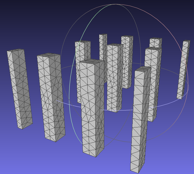
Remeshing with Meshlab using Filters → Remeshing, Simplification and Reconstruction → Remeshing: Isotropic Explicit Remeshing. While looking more complex, this mesh may be more preferred than the second figure above, as the triangles are closer to being equilateral.
To save the remeshed mesh, you go to File → Export Mesh As… and choose to save it as an stl file. Save this to the project folder in constant/triSurface/ with any name you like.
Step 3: surfaceFeatureExtract
#
Create the file system/surfaceFeatureExtractDict with the contents (modifying the mesh file name):
/*--------------------------------*- C++ -*----------------------------------*\
  =========                 |
  \\      /  F ield         | OpenFOAM: The Open Source CFD Toolbox
   \\    /   O peration     | Website:  https://openfoam.org
    \\  /    A nd           | Version:  6
     \\/     M anipulation  |
\*---------------------------------------------------------------------------*/
FoamFile
{
    version     2.0;
    format      ascii;
    class       dictionary;
    object      surfaceFeatureExtractDict;
}
// * * * * * * * * * * * * * * * * * * * * * * * * * * * * * * * * * * * * * //

Untitled2.stl //change this to match your file name
{
    // How to obtain raw features (extractFromFile || extractFromSurface)
    extractionMethod    extractFromSurface;

    extractFromSurfaceCoeffs
    {
        // Mark edges whose adjacent surface normals are at an angle less
        // than includedAngle as features
        // - 0  : selects no edges
        // - 180: selects all edges
        includedAngle   120;
    }
/*
    subsetFeatures
    {
        // Keep nonManifold edges (edges with >2 connected faces)
        nonManifoldEdges    yes;

        // Keep open edges (edges with 1 connected face)
        openEdges           yes;
    }
*/
    // Write options
    // Write features to obj format for postprocessing
    writeObj    yes;
}

// ************************************************************************* //
After this is saved, run the surfaceFeatureExtract tool in the project root directory, which creates an .emesh file in constant/triSurface.
Step 4: snappyHexMesh
#
Create the file system/snappyHexMeshDict with the contents of the file below, modifying it to point to the correct files. See the
appendix to see the full file.
If it’s been setup correctly, you can then run snappyHexMesh in the project root directory to create the new mesh. This will create new time-step folders with the mesh created in steps. If you wish for the mesh to be saved into constant/polyMesh, pass the -overwrite option. The alternative is to move it there yourself.
Running snappyHexMesh in Parallel
#
The system/decomposeParDict file needs to be created. This is the same file to be used for parallel simulation. Example contents of the file (with 4 processors - change this to your desired number of parallel processes):
/*--------------------------------*- C++ -*----------------------------------*\
  =========                 |
  \\      /  F ield         | OpenFOAM: The Open Source CFD Toolbox
   \\    /   O peration     | Website:  https://openfoam.org
    \\  /    A nd           | Version:  6
     \\/     M anipulation  |
\*---------------------------------------------------------------------------*/
FoamFile
{
    version     2.0;
    format      ascii;
    class       dictionary;
    object      blockMeshDict;
}
// * * * * * * * * * * * * * * * * * * * * * * * * * * * * * * * * * * * * * //

numberOfSubdomains 4; //modify this to suit the number of cores

method scotch;

// ************************************************************************* //
and in the project root directory, run decomposePar which creates processor* folders. snappyHexMesh is then invoked in parallel by
mpiexec -n 4 snappyHexMesh -parallel -overwrite
The mesh can then be reconstructed with the command reconstructParMesh in the project root directory.
Appendix #
/*--------------------------------*- C++ -*----------------------------------*\
  =========                 |
  \\      /  F ield         | OpenFOAM: The Open Source CFD Toolbox
   \\    /   O peration     | Website:  https://openfoam.org
    \\  /    A nd           | Version:  6
     \\/     M anipulation  |
\*---------------------------------------------------------------------------*/
FoamFile
{
    version     2.0;
    format      ascii;
    class       dictionary;
    object      snappyHexMeshDict;
}
// * * * * * * * * * * * * * * * * * * * * * * * * * * * * * * * * * * * * * //

// Which of the steps to run
castellatedMesh true;
snap            true;
addLayers       false;


// Geometry. Definition of all surfaces. All surfaces are of class
// searchableSurface.
// Surfaces are used
// - to specify refinement for any mesh cell intersecting it
// - to specify refinement for any mesh cell inside/outside/near
// - to 'snap' the mesh boundary to the surface
geometry
{
    Untitled2.stl // modify this
    {
        type triSurfaceMesh;
        name baffles; // modify this and use in below

        PatchInfo
        {
            type wall;
        }
    }
};


// Settings for the castellatedMesh generation.
castellatedMeshControls
{

    // Refinement parameters
    // ~~~~~~~~~~~~~~~~~~~~~

    // If local number of cells is &gr; maxLocalCells on any processor
    // switches from from refinement followed by balancing
    // (current method) to (weighted) balancing before refinement.
    maxLocalCells 100000;

    // Overall cell limit (approximately). Refinement will stop immediately
    // upon reaching this number so a refinement level might not complete.
    // Note that this is the number of cells before removing the part which
    // is not 'visible' from the keepPoint. The final number of cells might
    // actually be a lot less.
    maxGlobalCells 7000000;

    // The surface refinement loop might spend lots of iterations refining just a
    // few cells. This setting will cause refinement to stop if <= minimumRefine
    // are selected for refinement. Note: it will at least do one iteration
    // (unless the number of cells to refine is 0)
    minRefinementCells 0;

    // Allow a certain level of imbalance during refining
    // (since balancing is quite expensive)
    // Expressed as fraction of perfect balance (= overall number of cells /
    // nProcs). 0=balance always.
    maxLoadUnbalance 0.10;


    // Number of buffer layers between different levels.
    // 1 means normal 2:1 refinement restriction, larger means slower
    // refinement.
    nCellsBetweenLevels 1;


    // Explicit feature edge refinement
    // ~~~~~~~~~~~~~~~~~~~~~~~~~~~~~~~~

    // Specifies a level for any cell intersected by its edges.
    // This is a featureEdgeMesh, read from constant/triSurface for now.
    features
    (
        {
            file "Untitled2.eMesh"; // modify this
            level 1;
        }
    );


    // Surface based refinement
    // ~~~~~~~~~~~~~~~~~~~~~~~~

    // Specifies two levels for every surface. The first is the minimum level,
    // every cell intersecting a surface gets refined up to the minimum level.
    // The second level is the maximum level. Cells that 'see' multiple
    // intersections where the intersections make an
    // angle > resolveFeatureAngle get refined up to the maximum level.

    refinementSurfaces
    {
        baffles // modify this to match name defined earlier
        {
            // Surface-wise min and max refinement level
            level (2 2);
        }
    }

    // Resolve sharp angles
    resolveFeatureAngle 30;


    // Region-wise refinement
    // ~~~~~~~~~~~~~~~~~~~~~~

    // Specifies refinement level for cells in relation to a surface. One of
    // three modes
    // - distance. 'levels' specifies per distance to the surface the
    //   wanted refinement level. The distances need to be specified in
    //   descending order.
    // - inside. 'levels' is only one entry and only the level is used. All
    //   cells inside the surface get refined up to the level. The surface
    //   needs to be closed for this to be possible.
    // - outside. Same but cells outside.

    refinementRegions
    {
    }


    // Mesh selection
    // ~~~~~~~~~~~~~~

    // After refinement patches get added for all refinementSurfaces and
    // all cells intersecting the surfaces get put into these patches. The
    // section reachable from the locationInMesh is kept.
    // NOTE: This point should never be on a face, always inside a cell, even
    // after refinement.
    locationInMesh (0 0 0.1);


    // Whether any faceZones (as specified in the refinementSurfaces)
    // are only on the boundary of corresponding cellZones or also allow
    // free-standing zone faces. Not used if there are no faceZones.
    allowFreeStandingZoneFaces true;
}


// Settings for the snapping.
snapControls
{
    //- Number of patch smoothing iterations before finding correspondence
    //  to surface
    nSmoothPatch 3;

    //- Relative distance for points to be attracted by surface feature point
    //  or edge. True distance is this factor times local
    //  maximum edge length.
    tolerance 4.0;

    //- Number of mesh displacement relaxation iterations.
    nSolveIter 100;

    //- Maximum number of snapping relaxation iterations. Should stop
    //  before upon reaching a correct mesh.
    nRelaxIter 5;

    nFeatureSnapIter 10;
}


// Settings for the layer addition.
addLayersControls
{
    // Are the thickness parameters below relative to the undistorted
    // size of the refined cell outside layer (true) or absolute sizes (false).
    relativeSizes true;

    // Per final patch (so not geometry!) the layer information
    layers
    {
        baffles // modify this to match name defined earlier
        {
            nSurfaceLayers 5;
        }
    }

    // Expansion factor for layer mesh
    expansionRatio 1.1;

    // Wanted thickness of final added cell layer. If multiple layers
    // is the thickness of the layer furthest away from the wall.
    // Relative to undistorted size of cell outside layer.
    // See relativeSizes parameter.
    finalLayerThickness 0.8;

    // Minimum thickness of cell layer. If for any reason layer
    // cannot be above minThickness do not add layer.
    // Relative to undistorted size of cell outside layer.
    minThickness 0.1;

    // If points get not extruded do nGrow layers of connected faces that are
    // also not grown. This helps convergence of the layer addition process
    // close to features.
    nGrow 0;


    // Advanced settings

    // When not to extrude surface. 0 is flat surface, 90 is when two faces
    // are perpendicular
    featureAngle 60;

    // Maximum number of snapping relaxation iterations. Should stop
    // before upon reaching a correct mesh.
    nRelaxIter 3;

    // Number of smoothing iterations of surface normals
    nSmoothSurfaceNormals 1;

    // Number of smoothing iterations of interior mesh movement direction
    nSmoothNormals 3;

    // Smooth layer thickness over surface patches
    nSmoothThickness 2;

    // Stop layer growth on highly warped cells
    maxFaceThicknessRatio 0.5;

    // Reduce layer growth where ratio thickness to medial
    // distance is large
    maxThicknessToMedialRatio 0.3;

    // Angle used to pick up medial axis points
    minMedianAxisAngle 90;

    // Create buffer region for new layer terminations
    nBufferCellsNoExtrude 0;

    // Overall max number of layer addition iterations
    nLayerIter 50;
}


// Generic mesh quality settings. At any undoable phase these determine
// where to undo.
meshQualityControls
{
    //- Maximum non-orthogonality allowed. Set to 180 to disable.
    maxNonOrtho 65;

    //- Max skewness allowed. Set to <0 to disable.
    maxBoundarySkewness 20;
    maxInternalSkewness 4;

    //- Max concaveness allowed. Is angle (in degrees) below which concavity
    //  is allowed. 0 is straight face, <0 would be convex face.
    //  Set to 180 to disable.
    maxConcave 80;

    //- Minimum projected area v.s. actual area. Set to -1 to disable.
    minFlatness 0.5;

    //- Minimum pyramid volume. Is absolute volume of cell pyramid.
    //  Set to a sensible fraction of the smallest cell volume expected.
    //  Set to very negative number (e.g. -1E30) to disable.
    minVol 1e-13;
    minTetQuality 1e-30;

    //- Minimum face area. Set to <0 to disable.
    minArea -1;

    //- Minimum face twist. Set to <-1 to disable. dot product of face normal
    //  and face centre triangles normal
    minTwist 0.02;

    //- Minimum normalised cell determinant
    //  1 = hex, <= 0 = folded or flattened illegal cell
    minDeterminant 0.001;

    //- minFaceWeight (0 -> 0.5)
    minFaceWeight 0.02;

    //- minVolRatio (0 -> 1)
    minVolRatio 0.01;

    // must be >0 for Fluent compatibility
    minTriangleTwist -1;


    // Advanced

    //- Number of error distribution iterations
    nSmoothScale 4;
    //- Amount to scale back displacement at error points
    errorReduction 0.75;
}


// Advanced

// Merge tolerance. Is fraction of overall bounding box of initial mesh.
// Note: the write tolerance needs to be higher than this.
mergeTolerance 1E-6;


// ************************************************************************* //